
THE CURRENT METHOD OF TESTING CIRCUIT BREAKERS
BY MICHAEL SKELTON
Kelvatek
Background
One of the most critical devices on any electricity network is the circuit breaker which can be described as the silent sentinel, standing guard over the network and only being called into action when a fault occurs. The circuit breaker needs to operate within its composite tripping time (relay trip time plus circuit breaker main contact opening time) to ensure correct discrimination with upstream circuit breakers and, therefore, minimize the number of customers disconnected during a fault operation. A slow tripping circuit breaker will not only result in unnecessary disruptions to electricity supplies, but maintaining high fault currents for extended durations can stress the network and cause damage to plant and equipment. Often the problem that caused a slow trip is temporarily cleared during the first trip operation because friction in the mechanism is reduced by spreading lubrication during the motion of tripping. Traditional diagnostic testing procedures usually require the circuit breaker to be isolated and removed from service; therefore, not only has the opportunity to detect the cause of the defect been missed but also the tests do not focus on the condition of the operating mechanism apart from overall speed of operation.
Conventional Circuit Breaker Testing
Conventional testing has normally required removing the circuit breaker from service. However, isolating the circuit breaker is time consuming as it requires a planned outage involving the issue of switching instructions and safety documents and will often involve several engineers or technicians on site. This process resulted in vital information relating to the first trip not being captured and often the problem that caused a slow trip in a circuit breaker was temporarily cleared during this first trip operation. When a slow trip operation occurred the focus tended to be on timing tests to determine if the problem lay within the protection relay or the circuit breaker operating mechanism. Rarely were the problems due to slow operation of the protection relay, especially if they were the electronic or microprocessor based type. Occasionally problems occurred with the older electromechanical type relays due to friction in the moving parts such as the induction disc which would be revealed during secondary injection tests. Timing of the circuit breaker main contacts from initiation of a trip to main contact opening merely indicated the circuit breaker was operating within its design specification.
Therefore, the initial tests were inconclusive, so the focus then turned to inspecting the main operating mechanism and lubricating the numerous mechanical components. In some cases this further compounded the problem as the wrong type of lubricant was used, especially with the advent of spray penetrants which could be liberally applied. This caused an organic chemical reaction between the solvent and propellant (within the penetrant) and the soap (within the grease) resulting in varnish which caused the mechanism to stick. Instead of fixing the problem that caused the slow trip, the effort in testing and maintaining the circuit breaker was largely counterproductive.
Diagnostic Testing for Slow Tripping Circuit Breakers
The failure of conventional timing tests to diagnose the causes of slow tripping circuit breakers lead to the search for a technique that would pinpoint the cause during the critical first trip. Although timing tests can confirm that a circuit breaker’s overall operation is within set limits, it was discovered that monitoring the current flowing through the trip coil provided a very powerful methodology for analyzing the readiness of a circuit breaker to trip. Trip coil profiling was developed as a condition monitoring technique where deviation from a standard profile could help to pinpoint a potential problem within either the trip coil or the circuit breaker’s main operating mechanism.
Analysis of a Trip Coil Profile
The trip coil has both electric and magnetic circuits. Tripping action is typically due to the action of a plunger moving within an energized coil. This electromagnetic circuit has reluctance in the magnetic part as well as inductance and resistance in the electrical part. Normally, in most electrical circuits, we can think of the inductance as being fixed. However, in the trip coil, as the plunger moves, the reluctance of the magnetic circuit is reducing which means the inductance in the electric circuit is increasing. The applied voltage, which is a constant (apart from a small voltage drop), is proportional to the rates of change of both current and inductance. As the rate of change of inductance goes up the rate of change of current must go down and vice-versa. Hence, an instantaneous drop in the rate of rise of the inductance due to the plunger striking the latch or the end-stop will cause an instantaneous rise in the rate of change of current.
Diagram 1 shows a typical trip coil profile with its distinct shape where each stage of the trip coil mechanism can be identified through its operation and problems identified if the profile deviates from a signature trace.
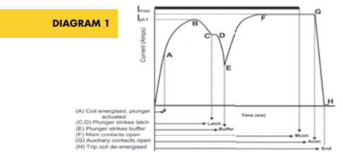
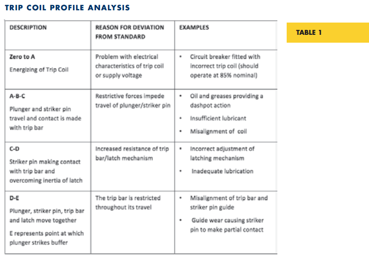
Table 1 provides examples of what would cause a deviation in any section of the profile curve. These examples are not exhaustive and can be simulated on a trip coil mechanism by varying the parameters that cause deviations, capturing the current profile, and overlaying it on a signature profile. Each type of circuit breaker will have its own characteristic profile; therefore, it is essential that this signature profile is acquired. Comparisons can then be made with profiles captured during on-site testing of the first trip operation and subsequent trip operations to identify potential defects.
Development of Portable Technology for Measuring Trip Coil Profiles
Initially the monitoring of trip coil profiles required the hard wiring of equipment into the circuit breaker; however, this was cost prohibitive and could only be justified for circuit breakers located at extremely critical nodes on the network. The development of portable, light weight, handheld devices with noninvasive connections to monitor the key current and voltage parameters has revolutionized the testing of circuit breakers. The process of testing a circuit breaker only takes a few minutes, enabling a condition assessment of the operating mechanism to be obtained during the first trip operation. As well as indicating the health of the circuit breaker trip and close coil mechanisms, other useful parameters are obtained which include:
• measuring the main contact operating time
• measuring the auxiliary contact operating time
• checking the integrity of control circuit wiring
• indicating problems with dc supply
Furthermore, the information is immediately available for on-site analysis, and corrective maintenance can be targeted at a defect.
It is becoming increasingly important to make connections within the circuit breaker cubicle to ensure that the right circuits are being monitored. Some modern circuit breakers use capacitive charged power supplies, so it is important that the current probe which monitors the dc current to the trip coil, is connected close to the trip coil.
The advantage of a portable handheld device means that it can be considered as an invaluable addition to the maintenance technician’s toolkit that can be used at any circuit breaker location.
Michael Skelton is the Product Manager for the Profile P3. He previously worked at Northern Ireland Electricity (NIE) for 33 years and has extensive experience in the following areas: design of rural protection schemes for the 11 kV overhead network, low voltage cable fault location, testing and commissioning of distribution switchgear, high voltage network planning, and general operational experience on the 11 kV and low voltage distribution network.
In his role as Emergency Response Manager for NIE, he was responsible for implementing an emergency response business which included centralized call handling and dispatch, dedicated fault restoration and repair teams, the amalgamation of the three distribution control centres into one new control centre supported by fully integrated network management, control room display, and SCADA systems.
BY MICHAEL SKELTON
Kelvatek
To view original article, please go here.
Recent Comments